Note 2 in the Design Notes series covering stormwater detention storage was originally issued in August 2012 and revised in January 2023.
Stormwater Detention Storage Design
The design of stormwater detention storage systems within the City of Greater Geelong shall comply with the following criteria.
This Design Note shall be read in conjunction with the IDM. Where the IDM and this Design Note are in conflict, this Note shall take precedence.
For private lot scale stormwater detention use IDM Clause 19, table 13 to determine a permissible site discharge (PSD) at the legal point of discharge (LPOD).
Design approaches
In general, hydrodynamic performance should determine the optimum size and shape of a flood and storm water detention basin (DB) rather than its catchment size or volumetric capacity.
That means, hydraulic routing (modelling), incorporating the intended detention systems, is required for designing such basins. Ideally, the City (City of Greater Geelong) expects undertaking the below or similar iterative process for determining the size and shape of a DB:
- Identifying the suitable location and land area available for the basin.
- Concept planning of the basin by grossly estimating size and shape of the basin.
- Hydraulic modelling, incorporating the DB, of the areas likely to be impacted by it.
- Understanding the retardation effect from inflow, outflow and stage hydrographs.
- Assessing pre and post flood risks along with the impact of the basin.
- Repeating the above steps 1-5 until a satisfactory outcome is achieved.
Depending on the criticality of a DB regarding its location in the catchment and various hydraulic influences, designing of such basin involving a simplistic process is acceptable. If the inflow catchment is reasonably small, limited to 10 hectares (ha), the simplistic process may involve flow estimation using Rational Formula (or composite form of it as required, that is, Q = i ∑CjAj) and Modified Rational Method or hydrologic routing (based on Continuity or Storage Equation).
For catchments larger than 10 ha but up to 400 ha, the Rational Formula can be used for preliminary estimation of the DB sizes for the purpose of setting up hydraulic models. Various hydrologic computations (for example, Unit Hydrograph Method) and routing programs have their own parameters and requirements, discussion on which are beyond the scope of this Design Note except the Runoff Coefficient of Rational Formula.
Based on the catchment areas, Table 1 below summarises the computational approaches to be involved to estimate flow, volume, size and shape of a detention basin.
Table 1 - Summary of computational approaches
| Computational elements vs Catchment area | Catchment area not over 10 hectares (ha) | Catchment area over 10 ha |
|---|---|---|
| Estimation of rural or pre-development inflow | Rational Formula or runoff routing program (without any hydraulic modelling at all) is acceptable. | For initial estimation, use Rational Method or a runoff routing program. The size and shape to be finalised based on hydrodynamic performance of the system regarding flow retardation, flood risk, onsite and offsite impacts of the basin etc. |
| Size, shape and storage volume of detention basin | Use a runoff routing program or method listed in Table 2 to size a storage basin including design of outlet (based on HGL and tailwater level). |
If the flow computations are based on hydrologic routing programs that mostly rely on non-deterministic, fictitious or ineffective evaluation of parameters and substantial assumptions on which results are very sensitive, the peak flows must be calibrated to the flows obtained from Rational Formula.
Methods and tools for sizing of detention storage
Table 2 lists the computational methods and tools to be used depending on the drainage area of two types of detention basins (DB) - On-site Detention (OSD) storages and the retarding basins (RB) - that are to be taken over by the City. The basin size is expected to be highly dependent on the design rainfall based on Annual Exceedance Probability (AEP) which is often adopted as 1 in 100, 20 or 10. The retardation effect of the basin should be reported as superimposed inflow, outflow and stage hydrographs.
Table 2 - Methods and tools for sizing of detention storages
| Type of storage | Site or catchment area, A | Sizing method | Comments |
|---|---|---|---|
| On-site Detention (OSD) - DBs not to be taken over by the City | A not over 10 ha | Modified Rational Method Or listed tools below | Sizing based on hydrological routing is acceptable to the City. |
| Over 10 ha | XPSTORM HEC-RAS MIKE DRAINS RORB | The City expects hydraulic routing for finalising the size and shape of basins. Modified Rational Method or hydrologic routing may be acceptable depending on the hydraulic significance of the basin. | |
| Detention basins to be taken over by the City of Greater Geelong | A not over 10 ha | Modified Rational Method Or listed tools below | The City may accept sizing based on hydrological routing depending on the location and hydraulic significance of the basin. Please seek confirmation on this in the beginning of planning. |
| Over 10 ha | XPSTORM HEC-RAS MIKE DRAINS RORB | The City expects hydraulic routing for finalising the size and shape of basins. Modified Rational Method or hydrologic routing may be acceptable depending on the hydraulic significance of the basin. |
Rational Method
Runoff Coefficient
Table 3 contains the runoff coefficients that shall be used for flow estimation using Rational Formula. The imperviousness as fraction of catchment or subarea (for composite analysis of Rational Formula) sizes shall be estimated utilising Melbourne Water’s MUSIC Guidelines 2018 (originally 2010) along with other available information, such as, satellite/aerial photos, maps, site visits etc.
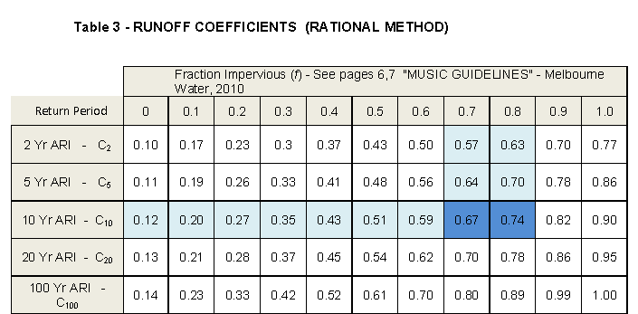
The blue shades above show how to find out runoff coefficient C10 for an f between 0.7 and 0.8
Time of Concentration
The time for overland sheet flows shall be considered as Time of Concentration tc (which is often considered as the critical rainfall duration in the Rational Formula) and may be based on the Kinematic Wave Equation unless found to be unrealistic:
tc = 6.94(L.n*)0.6 / (I0.4.S0.3) minutes
Where L is length of flow path in metre, n* is surface retardance coefficient, I is rainfall intensity (mm/h), S is slope (m/m).
If flow path is well-defined (naturally or by man-made), Manning Formula for Open Channel Flow computations or a relevant software can be used to calculate the flow velocity and then to estimate travel time which may be considered as the Time of Concentration, tc. In absence of a convincible determination of tc, it should be estimated from the professional experience and judgement by examining the topography, flow paths, urbanisation, infrastructures etc.
Design rainfall
The appropriate rainfall data and/or IFD charts to be downloaded from the Australian Rainfall and Runoff (ARR) Data Hub website to determine the design rainfall.
Page last updated:
We are glad that you find this page helpful!
Submitting feedback... Please wait.
An error occured! Please try again.
Feedback submitted successfully!
Thank you for your feedback. We value your input and will use it to improve our services.